After fiddling with the materials I discovered that the 'X' formations placed on the top and bottom of the bridge seemed to as effective as just a beam connecting to opposite corners. So to cut down on cost even further I switched out the 'X' formations on the top and bottom for the yellow 3.375" chord. In the whole design process I have learned that ideas will have to change because not all ideas that you have when designing something can be just transferred into building the bridge. Your ideas may be interfered with depending on the materials available. Also, after seeing the designs of my fellow partners I believe that there will not be too much arguing between what the final design should be.
Wednesday, May 2, 2012
A2- LaChance
When approaching this assignment I knew right off the bat that the design I had for the WPBD program was not going to be transferred into KNex, so I decided to go back to the basics. First I looked and the model bridges that were given to us in the WPBD program and made to one that seemed to be the most structurally sound out of the three with some modifications. Instead of just having one beam go from corner to corner of each box I decided that and 'X' formation would be sturdier. I also used a select few of the materials available because it made the building of the actual bridge easier. After taking some measurements the bridge came out to be 2' long x 3" wide x 3" tall.
After fiddling with the materials I discovered that the 'X' formations placed on the top and bottom of the bridge seemed to as effective as just a beam connecting to opposite corners. So to cut down on cost even further I switched out the 'X' formations on the top and bottom for the yellow 3.375" chord. In the whole design process I have learned that ideas will have to change because not all ideas that you have when designing something can be just transferred into building the bridge. Your ideas may be interfered with depending on the materials available. Also, after seeing the designs of my fellow partners I believe that there will not be too much arguing between what the final design should be.
Week 5 Blog Post
During our engineering lab last week, librarian Jay Bhatt came in to talk to us. Some people had submitted questions to him about anything regarding this class which unfortunately he did not have a sufficient amount of time to cover many of the questions. What he was able to tell us was how to go about using the library resources to guide us on making our bridges. He also gave us his contact information so that if we needed to we could ask him any questions. Also in lab we discussed how we may not be able to make the designs we did in WPBD due to the constraints of the KNex pieces. We were also given the following parameters; the bridge had to be at least two feet long and have a flat surface for a block to place on top of the bridge. After listening to everything that had to be said beforehand, each group went back to their tables and began to get a feel for the KNex and how they can be used.
When messing around with possible structures there were some visible differences. WPBD is able to show the stresses put on each point of the bridge but the Knex has to forces in 3 dimensions instead of 2. Because we can’t measure the stresses using the KNex it would be impossible to find out what would need to be changed unless we test it. In WPBD you could use different types of materials and beams, but with KNex there are only different sizes of the chords that we can use. I personally enjoy working with KNex so I have the mindset that this part of the lab will be pretty exciting.
-Robert LaChance
When messing around with possible structures there were some visible differences. WPBD is able to show the stresses put on each point of the bridge but the Knex has to forces in 3 dimensions instead of 2. Because we can’t measure the stresses using the KNex it would be impossible to find out what would need to be changed unless we test it. In WPBD you could use different types of materials and beams, but with KNex there are only different sizes of the chords that we can use. I personally enjoy working with KNex so I have the mindset that this part of the lab will be pretty exciting.
-Robert LaChance
Tuesday, May 1, 2012
A2-Tillman
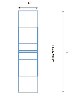
This bridge is based off of a simple but effective bridge design I came up with while using West Point Bridge Designer. This is a simple truss bridge with the addition of small top and bottom supports. These supports are present to provide support to the middle of the bridge so it does not split down the center when weight is place on it. The bridge is the minimum length at two feet long with eight inch height and six inch width.
Over the course of this design, I simplified my bridge to cut down on costs. I moved the bulk of my bridge to the center of the bridge instead of overtop as in my original design in WPBD. In addition to this, I changed my trusses from triangles to "X" designs. I did this to provide the bridge with added support. I also strengthened many of the beams to provide extra support.
While designing this bridge, I learned the importance of the materials used. I also learned that designing a bridge takes patience. A great amount of testing is required when designing any bridge. The most important thing I learned is to listen to my teammates. Everyone in my group has great ideas and if we put all of our great ideas together, we should come out with the most effective bridge design at the lowest possible cost.
A2-Watson
1. I based my design off one of my first bridge designs in
Westpoint Bridge Design. From the side
you can see a bunch of triangles. These
triangles alternate from being right side up to up side down. In the middle of the design you can see the
two supports make an X. I felt that the
middle of the bridge would be the weakest point so I crossed two supports
there. I used three different types of
beams and 3 different types of gusset plates.
The beams I use were 1-1/4, 2-1/8, and 3-3/8. The gusset plates I used were 180-degree
grooved gusset plates, 360-degree gusset plates and, 45-degree gusset
plates.
2. Elevation View
3. Plan View
2. Elevation View
4. Cost
5. My design changed once during drafting. The one thing I did change was the crossing
beams in the middle. Like I said above I
did this to add strength to what I thought to be the weakest part of the
bridge.
6. While doing the design I learned that you do not want to put
too much in because it will raise the cost of the bridge. I do wish that I had Knexts to bring home
because it is hard to imagine in your head what will fit and what will not.
Week 5 Blog Post
Last week the engineering librarian Jay Bhatt came in to
talk to us. The previous week we had
submitted questions and he briefly touched base on some of them. He explained how to use the library and other
tools we might need in order to research bridges. He also said to contact him if we had any
questions. Before he came in and talked
we discussed issues concerning the Knex bridges. We went over how much each piece would cost
and the constraints of the bridge. The
bridge had to be at least two feet long and have a flat surface for a block to
placed. After we broke up into smaller
groups we got to play around and get the feel for the Knex.
Knex and
Westpoint bridge design are similar in that you get a feel for creating a
bridge and you can play with different designs.
What Westpoint bridge design lacks in is that it is unrealistic but the
Knex make up for this. In Westpoint
bridge design the bridge would bend unrealistically. The Knex will not bend like this and will
break before they even get to that point.
In Westpoint bridge design you could play around with different types of
materials and beams, but when using Knex we are limited to the same type of
plastic and beam, they only differ in size.
One other thing that I noticed is that the Knex bridges are much more
time consuming to make. It is also hard
to tell where the breaking points are on the Knex bridges. Since this part of the project is more hands
on I feel like we will learn a lot more.
I can’t wait to start building!
-John Watson
Monday, April 30, 2012
Week 5 Blog Post
There are many differences between the West Point Bridge Designer program and the actual construction of KNex. The most obvious difference is the realism in the constructing of KNex. When building with KNex, a physical bridge is created compared to a computer-simulated bridge on WPBD. This KNex bridge can be tested using weights and other methods of real world testing. There is also a difference in that WPBD can indicate the exact area of the bridge that fails and perform hundreds of weight and tension calculations in seconds. This is not as easy when testing a KNex bridge.
There are also many similarities between the two products. Both methods of bridge design use beams and joints to produce a bridge to be tested. Stronger, more expensive pieces can be substituted with weaker, but less expensive pieces and vice-versa. Doing this can save money by placing inexpensive pieces in areas where it isn't as necessary to support such heavy loads. Both end results are tested to hold the maximum amount of weight at the lowest possible cost.
Last week in lab, we began to experiment with KNex and get an idea of how our bridge design will be translated to a physical structure. We tried out many different ideas from our WPBD models and were able to come up with what we think will be a good, strong, inexpensive design. I'm looking forward to getting to work on the final bridge design and to begin testing. This week in lab, we will begin putting together our bridge design with KNex, testing is optional. I think we will make great progress with the design but I doubt we will be ready to test by the end of lab. I'm excited and optimistic.
There are also many similarities between the two products. Both methods of bridge design use beams and joints to produce a bridge to be tested. Stronger, more expensive pieces can be substituted with weaker, but less expensive pieces and vice-versa. Doing this can save money by placing inexpensive pieces in areas where it isn't as necessary to support such heavy loads. Both end results are tested to hold the maximum amount of weight at the lowest possible cost.
Last week in lab, we began to experiment with KNex and get an idea of how our bridge design will be translated to a physical structure. We tried out many different ideas from our WPBD models and were able to come up with what we think will be a good, strong, inexpensive design. I'm looking forward to getting to work on the final bridge design and to begin testing. This week in lab, we will begin putting together our bridge design with KNex, testing is optional. I think we will make great progress with the design but I doubt we will be ready to test by the end of lab. I'm excited and optimistic.
Wednesday, April 25, 2012
Week 4 Blog Post:
While using the West Point Bridge Design program it became very clear that there were clearly some pros to the system as well as some cons. To start off on the positive side the WPBD program clearly helped as a guiding tool for those who have never used the program or ever worked with bridges before. Also, the program gave measurements of the stresses that would occur when weight was added. Some others may think that the exaggeration of the sagging of the bridge in the program would be a con to it but there is a way to turn off the exaggeration when in the animation screen. Because of this I do not consider it to be a pro or a con. However, there was a specific con that stood out right away to me as well as a lot of others. The WPBD does not take into consideration any external forces the bridge may encounter. Some external forces that may act on the bridges may include but are not limited to rain, snow, and wind. Also there was only one vehicle crossing the bridge at a time instead of a bunch of vehicles of varying shapes and sizes. Finally, the bridge in the program is not able to take into account the changes that occur of a long span of time due to wear and tear. Overall I did find the WPBD program to be a helpful tool, but only up to a certain extent.
While in class last week we looked at some of the bridges that people designed for that week. The lowest costing bridge was around $250,000 which was far less than the bridge that I submitted which was around $400,000. During class each group was asked to create another bridge to be the cheapest design which our group got the cost down to $250,000, but even this is probably still not close enough to the lowest costing bridge. While still very intrigued about how to design the lowest costing yet still effective bridge in the WPBD program I kept at it and was able the create a bridge that cost just under $230,000. Unfortunately I cannot submit this bridge to get the extra credit point, but that does not matter to me as much. Now I look forward to the week ahead to the transition from the WPBD program to using Knex to build a bridge. When doing this the group as a whole will have to meet more often than the previous weeks to create the best bridge possible.
-Robert LaChance
Subscribe to:
Posts (Atom)